RS-232
OPTION
INSTALLING THE
RS-232 OPTION BOARD
Install
the RS-232 option
board as follows
(refer to Figure
8-1):
 Caution: the
meter has no power-on
switch, so it will
be in operation
as soon as you
apply power.
Important: Disconnect
the power from
the unit before
installing this
option board.
1. Remove
the protective
back panel and
slide the meter
out of the case.
2. Hold
the RS-232 option
card in a vertical
position, with
the J2 connector
facing the back
of the meter.
3. Line
up the P1 connector
on the RS-232 board
with the J1 pins
on the main board.
Push down to secure.
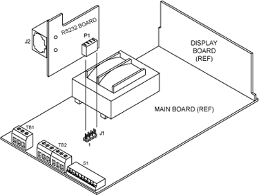
Figure 8-1. Installing
the RS-232 Option
Board
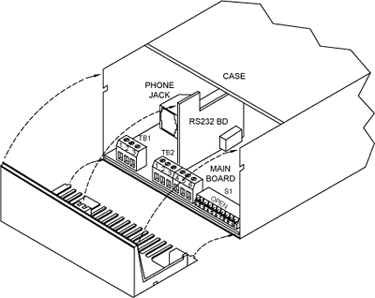
Figure 8-2. Protective
Back Panel
4.
Slide meter back
into the case.
5. Install
the protective
rear panel to secure
the board (refer
to Figure 8-2):
a. Align
the two bottom
front edges of
the protective
panel with the
corresponding
groves on the
meter case.
b. Align
the top left
groove of the
protective panel
with the RS-232
board.
c. Snap
protective panel
closed.
REMOTE
PROGRAMMING
The meter may accept
an RS-232 card
for communications.
The card enables
the meter to receive
setup commands
and data, and send
measurement values
and current setup
data to a computer.
The meter operates
at either 1200
or 9600 baud, 7
data bits, even
parity and 1 stop
bit. It emulates
DCE (data communication
equipment) and
uses a handshake
line while sending
data, but none
while receiving
data. A 4-wire
cable is the maximum
required for the
following communications:

When you connect
your meter to a
computer, such
as an IBM PC, and
the meter receives
one of 8 commands
(P, G, W, R, V,
SC, SG and SP)
the meter interrupts
its program, receives
the message, takes
appropriate action,
and then starts
over with a new
measurement. No
handshake is required
because the meter
devotes its full
attention to receiving
the command data
from the computer.
In the other direction,
the meter sends
measurement and
confirming setup
data to the computer
under one of 2
handshake (RTS)
modes.
Message Handshake
- The RTS line
is checked when
the device is ready
to send measurement
data. If the RTS
is true, it sends
the complete message
data without interruption
even if the RTS
goes false in the
middle of transmission.
If the RTS is false,
it skips sending
the data completely
and continues with
the next measurement.
Character Handshake
- The device checks
the RTS input before
sending each character
and sends characters
only while the
RTS is true.
ASCII
OUTPUT
The meter sends
measurement data
according to the
following fixed
formats of 9 or
8 characters. Each
character is sent
as a 7-bit ASCII
code character
with even parity,
and may be blank
(ASCII 32)
9-Character
Format
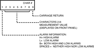
Figure 8-3. ASCII
Output 9-Character
Message (COnFIG=XXXXX0)
As
Figure 8-3 details,
the 1st character
represents alarm
information and
provides one of
the following:
H = High Alarm,
L = Low Alarm,
B = Both High and
Low Alarms or Space
= Neither High
nor Low Alarms.
Characters 1
through 8 represent
the measurement
value as shown
on the front-panel.
If positive, there
are 6 digits and
a decimal point;
if negative, there
is a minus sign
with 5 digits and
a decimal point.
Blanks are sent
in place of leading
zeros. If the value
overflows the 6-digit
limit, it is sent
in exponential
format up to a
maximum of 9.99
E9 or -9.9 E9.
The final character
is a carriage return.
8-Character
Format
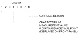
Figure 8-4. ASCII
Output 8-Character
(COnFIG=XXXXX1)
Characters 1
through 7 represent
the value on the
display (6 digits
and a decimal point).
The final character,
(character 8),
is a carriage return.
SETUP
DATA
'Get'
or 'Read' commands
send setup data
to the computer
for verification.
Setup data is sent
and received as
ASCII characters
representing the
16 hex characters
0-9; A-F. Each
hex character represents
4 bits or 16 pieces
of information.
The 7-bit ASCII
characters are
shown with a leading
even-parity bit,
as shown in Table
8-1.
Hex
Character/Bit
Pattern Information
Table
8-1
|
Hex
Character
|
Bit
Pattern
|
Hex
Character
|
Bit
Pattern
|
|
0
|
0011
0000
|
8
|
1011
1000
|
|
1
|
1011
0001
|
9
|
0011
1001
|
|
2
|
1011
0010
|
A
|
0100
0001
|
|
3
|
0011
0011
|
B
|
0100
0010
|
|
4
|
1011
0100
|
C
|
1100
0011
|
|
5
|
0011
0101
|
D
|
0100
0100
|
|
6
|
0011
0110
|
E
|
1100
0101
|
|
7
|
1011
0111
|
F
|
1100
0110
|
The
setup data consists
of a total of 44
nibbles of information
that are sent and
received in the
following order:
Setup
Order Information
Table 8-2
|
Display
|
Parameter
|
#
of Nibbles
|
|
-------
|
Analog
Out Scale*
|
2
|
|
|
Analog
Out Offset*
|
4
|
|
|
Calibration
|
2
|
|
SP
HI
|
Setpoint
High
|
6
|
|
SP
LO
|
Setpoint
Low
|
6
|
|
OFFSEt
|
Offset
|
6
|
|
SCALE
|
Scale
|
6
|
|
-------
|
Gate
Time
and Time
Out
|
4
|
|
-------
|
Analog
Output
Control*
|
2
|
|
COnFIG
|
Configuration
|
2
|
|
dEC
Pt
|
Decimal
Point
|
2
|
|
Func
|
Function
|
2
|
*
Do not confuse
with "An LO"
and "An HI".
Each
parameter is sent
with the most-significant
nibble first. Each
bit may have stand-alone
significance or
may be part of
a binary number
according to the
following formats.
The binary value
0-255 is used to
calculate the analog
output value from
the display value
(refer to Figure
8-9). See also
Control Bit Storage
(refer to Figure
8-7).
Analog
Out Scale
(2 Nibbles
Each)

Figure
8-5
Analog
Out Scale
Storage
Format
|
Analog
Out Offset
(4 Nibbles
Each)

Figure
8-6
Analog
Out Offset
Storage
Format
|
NOTE: 256
generates 0 V (0
mA) and 51200 generates
10 V (20 mA).
ANALOG
OUT CONTROLS
An LO and An HI
menu items are
for coarse adjustment
of analog output.
The meter uses
these values to
calculate Analog
Scale and Offset.
Analog Scale is
one byte and stored
in location 3E.
Analog Offset is
2 bytes and is
stored in locations
3C and 3D. Location
2C is used for
storage of control
bits as follows:

Figure
8-7.
Storage
Format
|
The
decimal
point value
must be
1 through
6 (not
0 or 7).
Example:
A01000
= -0409.6
DP=2, -
Negative
Polarity |
GATE
TIME

Figure
8-8.
Binary
Value
|
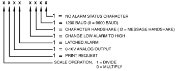
Figure
8-9.
Setup
Configuration
|
If MS byte is
1111 1111, meter
uses 00000000.
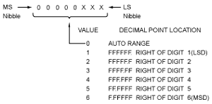
Figure
8-10.
Decimal
Point
Setup
|
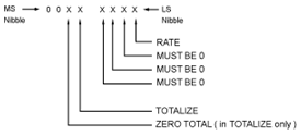
Figure
8-11.
Totalizer
Function
Setup
|
One, and only one
bit must be a 1
- except for the
totalizer bit,
which may also
have the zero total
bit set to a 1.
When the meter
receives the totalizer
bit, the zero total
bit causes the
value to be reset
to zero; otherwise,
the TOTALIZER value
is unaffected.
|